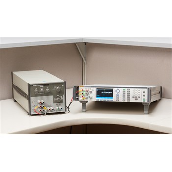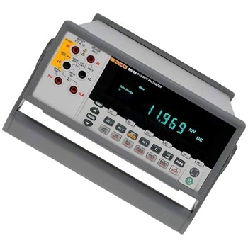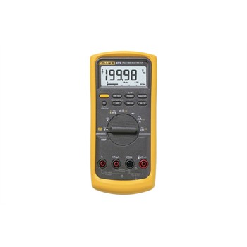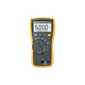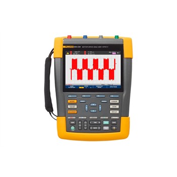

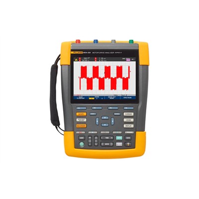
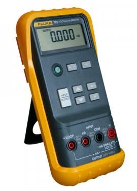
Fluke MDA-550 Series III Motor Drive Analyzer
Category: ELECTRICAL
Model: Portable Oscilloscope
Avaibility: AVAILABLE
Call For Price


Talk with one of our sales
Monday to Friday 8AM - 5PM WIB
021- 72791867
Fluke MDA-550 Series III Motor Drive Analyzer
Category: ELECTRICAL
Model: Portable Oscilloscope
Avaibility: AVAILABLE
Call For Price
Specifications: Fluke MDA-550 Series III Motor Drive Analyzer
Specifications: Fluke MDA-550 Series III Motor Drive Analyzer
| Measurement and Analysis Combinations | |||||
| Test point | Sub group | Reading 1 | Reading 2 | Reading 3 | Reading 4 |
| Motor drive input | |||||
| Voltage and current | |||||
| Phase-phase | V-A-Hz | V ac+dc | A ac+dc | Hz | |
| V peak | V peak max | V peak min | V pk-to-pk | Crest factor | |
| A peak | A peak max | A peak min | A pk-to-pk | Crest factor | |
| Phase-ground | V-A-Hz | V ac+dc | A ac+dc | Hz | |
| V peak | V peak max | V peak min | V pk-to-pk | Crest factor | |
| A peak | A peak max | A peak min | A pk-to-pk | Crest factor | |
| Voltage unbalance | Unbalance | V ac+dc | V ac+dc | V ac+dc | Unbalance |
| Peak | V pk-to-pk | V pk-to-pk | V pk-to-pk | ||
| Current unbalance | Unbalance | A ac+dc | A ac+dc | A ac+dc | Unbalance |
| Peak | A pk-to-pk | A pk-to-pk | A pk-to-pk | ||
| Motor drive DC bus | |||||
| DC | V dc | V pk-to-pk | V peak max | ||
| Ripple | V ac | V pk-to-pk | Hz | ||
| Motor drive output | |||||
| Voltage and current (filtered) | V-A-Hz | V PWM | A ac+dc | Hz | V/Hz |
| V peak | V peak max | V peak min | V pk-to-pk | Crest factor | |
| A peak | A peak max | A peak min | A pk-to-pk | Crest factor | |
| Voltage unbalance | Unbalance | V PWM | V PWM | V PWM | Unbalance |
| Peak | V pk-to-pk | V pk-to-pk | V pk-to-pk | ||
| Current unbalance | Unbalance | A ac+dc | A ac+dc | A ac+dc | Unbalance |
| Peak | A pk-to-pk | A pk-to-pk | A pk-to-pk | ||
| Voltage modulation | |||||
| Phase-phase | Zoom 1 | V PWM | V pk-to-pk | Hz | V/Hz |
| Zoom 2 | V peak max | V peak min | Delta V | ||
| Zoom 3 peak | V peak max | Delta V/s | Risetime peak | Overshoot | |
| Zoom 3 level | Delta V | Delta V/s | Risetime level | Overshoot | |
| Phase-ground | Zoom 1 | V PWM | V pk-to-pk | V peak max | V peak min |
| Zoom 2 | V Peak max | V peak min | Delta V | Hz | |
| Zoom 3 peak | V Peak max | Delta V/s | Risetime peak | Overshoot | |
| Zoom 3 level | Delta V | Delta V/s | Risetime level | Overshoot | |
| Phase-DC + | Zoom 1 | V PWM | V pk-to-pk | V Peak max | V peak min |
| Zoom 2 | V peak max | V peak min | Delta V | Hz | |
| Zoom 3 peak | V peak max | Delta V/s | Risetime peak | Overshoot | |
| Zoom 3 level | Delta V | Delta V/s | Risetime level | Overshoot | |
| Phase-DC - | Zoom 1 | V PWM | V pk-to-pk | V peak max | V peak min |
| Zoom 2 | V peak max | V peak min | Delta V | Hz | |
| Zoom 3 peak | V peak max | Delta V/s | Risetime peak | Overshoot | |
| Zoom 3 level | Delta V | Delta V/s | Risetime level | Overshoot | |
| Motor input | |||||
| Voltage and current (filtered) | V-A-Hz | V PWM | A ac+dc | Hz | V/Hz |
| V peak | V peak max | V peak min | V pk-to-pk | Crest factor | |
| A peak | A peak max | A peak min | A pk-to-pk | Crest factor | |
| Voltage unbalance | Unbalance | V PWM | V PWM | V PWM | Unbalance |
| Peak | V pk-to-pk | V pk-to-pk | V pk-to-pk | ||
| Current unbalance | Unbalance | A ac+dc | A ac+dc | A ac+dc | Unbalance |
| Peak | A pk-to-pk | A pk-to-pk | A pk-to-pk | ||
| Voltage modulation | |||||
| Phase-phase | Zoom 1 | V PWM | V pk-to-pk | Hz | V/Hz |
| Zoom 2 | V peak max | V peak min | Delta V | ||
| Zoom 3 peak | V peak max | Delta V/s | Risetime peak | Overshoot | |
| Zoom 3 level | Delta V | Delta V/s | Risetime level | Overshoot | |
| Phase-ground | Zoom 1 | V PWM | V pk-to-pk | V peak max | V peak min |
| Zoom 2 | V peak max | V peak min | Delta V | Hz | |
| Zoom 3 peak | V peak max | Delta V/s | Risetime peak | Overshoot | |
| Zoom 3 level | Delta V | Delta V/s | Risetime level | Overshoot | |
| Motor shaft | |||||
| Shaft voltage | Events off | V pk-to-pk | |||
| Events on | Delta V | Rise/fall time | Delta V/s | Events/s | |
| Motor drive input, output and motor input | |||||
| Harmonics | Voltage | V ac | V fundamental | Hz fundamental | % THD |
| Current | A ac | A fundamental | Hz fundamental | % THD/TDD |
| Measurement Function | Specification |
| DC voltage (V dc) | |
| Maximum voltage with 10:1 or 100:1 probe | 1000 V |
| Maximum resolution with 10:1 or 100:1 probe (voltage to ground) | 1mV / 10mV |
| Full scale reading | 999 counts |
| Accuracy at 4 s to 10 us/div | ± (1.5 % + 6 counts) |
| True-rms voltage (V ac or V ac + dc) (with DC coupling selected) | |
| Maximum voltage with 10:1 or 100:1 probe (voltage to ground) | 1000 V |
| Maximum resolution with 10:1 or 100:1 probe | 1 mv / 10 mV |
| Full scale reading | 999 counts |
| DC to 60 Hz | ± (1.5 % + 10 counts) |
| 60 Hz to 20 kHz | ± (2.5 % + 15 counts) |
| 20 kHz to 1 MHz | ± (5 % + 20 counts) |
| 1 MHz to 25 MHz | ± (10 % + 20 counts) |
| PWM voltage (V pwm) | |
| Purpose | To measure on pulse width modulated signals, like motor drive inverter outputs |
| Principle | Readings show the effective voltage based on the average value of samples over a whole number of periods of the fundamental frequency |
| Accuracy | As Vac+dc for sinewave signals |
| Peak voltage (V peak) | |
| Modes | Max peak, min peak, or pk-to-pk |
| Maximum voltage with 10:1 or 100:1 probe (voltage to ground) | 1000 V |
| Maximum resolution with 10:1 or 100:1 probe | 10 mV |
| Accuracy | |
| Max peak, min peak | ± 0.2 division |
| Pk-to-pk | ± 0.4 division |
| Full scale reading | 800 counts |
| Current (AMP) with current clamp | |
| Ranges | Same as V ac, Vac+dc or V peak |
| Scale Factors | 0.1 mV/A, 1 mV/A, 10 mV/A, 20 mV/A, 50mV/A, 100 mV/A, 200 mV/A, 400 mV/A |
| Accuracy | Same as Vac, Vac+dc or V peak (add current clamp accuracy) |
| Frequency (Hz) | |
| Range | 1.000 Hz to 500 MHz |
| Full scale reading | 9999 counts |
| Accuracy | ± (0.5 % + 2 counts) |
| Voltage/Herz ratio (V/Hz) | |
| Purpose | To show the measured V PWM value (see V PWM) divided by the fundamental frequency on vari- able ac motor speed drives |
| Accuracy | % Vrms + % Hz |
| Voltage unbalance drive input | |
| Purpose | To show the highest percentage difference of one of the phase vs average of the 3 true-rms voltages |
| Accuracy | Indicative percentage based on Vac+dc values |
| Voltage unbalance drive output and motor input | |
| Purpose | To show the highest percentage difference of one of the phase vs average of the 3 PWM voltages |
| Accuracy | Indicative percentage based on V PWM values |
| Current unbalance drive input | |
| Purpose | To show the highest percentage difference of one of the phase vs average of the 3 AC current values |
| Accuracy | Indicative percentage based on Aac+dc values |
| Current unbalance drive output and motor input | |
| Purpose | To show the highest percentage difference of one of the phase vs average of the 3 AC current values |
| Accuracy | Indicative percentage based on A ac values |
| Rise and fall time | |
| Readings | Voltage difference (dV), time difference (dt), voltage vs time difference (dV/dt), overshoot |
| Accuracy | As oscilloscope accuracy |
| Harmonics and spectrum | |
| Harmonics | DC to 51st |
| Spectrum ranges | 1…9 kHz, 9-150 kHz (20 MHz filter on), up to 500 MHz (voltage modulation) |
| Shaft voltage | |
| Events / second | Indicative percentage based on rise and fall time (Impulse discharges) measurements |
| Report data capture | |
| Number of screens | Typical 50 screens can be saved in reports (depends on compression ratio) |
| Transfer to PC | Using 32 GB or smaller 2 GB USB stick or mini-USB to USB cable or WiFi link and FlukeView™ 2 for ScopeMeter® |
| Probe settings | |
| Voltage Probe | 1:1, 10:1, 100:1, 1000:1, 20:1, 200:1 |
| Current Clamp | 0.1 mV/A, 1 mV/A, 10 mV/A, 20 mV/A, 50 mV/A, 100 mV/A, 200 mV/A, 400 mV/A |
| Shaft Voltage Probe | 1:1, 10:1, 100:1 |
| Safety | |
| General | IEC 61010-1: Pollution Degree 2 |
| Measurement | Measurement IEC 61010-2-030: CAT IV 600 V / CAT III 1000 V |
| Maximum voltage between any Terminal and Earth Ground | 1000 V |
| Max. input voltages | Via VPS410-II or VPS421 1000 V CAT III / 600 V CAT IV |
| BNC Input | A, B, C, D directly 300 V CAT IV |
| Max. Floating Voltage, test tool or test tool with VPS410-II / VPS421 voltage probe | From any terminal to earth ground 1000 V CAT III / 600 V CAT IV Between any terminal 1000 V CAT III / 600 V CAT IV |
| Working voltage between probe tip and probe reference lead | VPS410-II: 1000 V VPS421: 2000 V |
OTHER PRODUCT
We Offer Many Product For All Your Needs